In this note I will describe how to load colors into the Sega palette in assembler.
The final result in the Exodus emulator will look like this: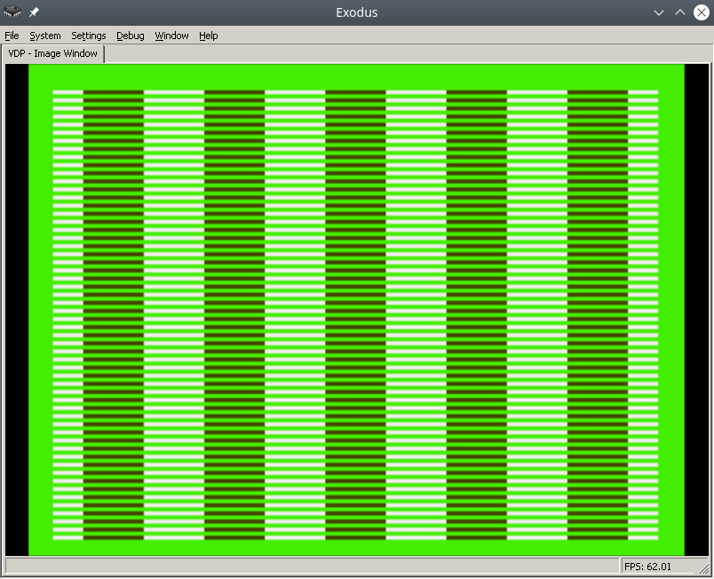
To make the process easier, find a pdf online called Genesis Software Manual (1989), it describes the whole process in great detail, in fact, this note is a commentary on the original manual.
In order to write colors to the VDP chip of the Sega emulator, you need to do the following:
- Disable TMSS protection system
- Write the correct parameters to the VDP registers
- Write the desired colors to CRAM
For assembly we will use vasmm68k_mot and a favorite text editor, for example echo. Assembly is carried out by the command:
Порты VDP
VDP чип общается с M68K через два порта в оперативной памяти – порт контроля и порт данных.
По сути:
- Через порт контроля можно выставлять значения регистрам VDP.
- Также порт контроля является указателем на ту часть VDP (VRAM, CRAM, VSRAM etc.) через которую передаются данные через порт данных
Интересная информация: Сега сохранила совместимость с играми Master System, на что указывает MODE 4 из мануала разработчика, в нем VDP переключается в режим Master System.
Объявим порты контроля и данных:
vdp_data_port = $C00000
Отключить систему защиты TMSS
Защита от нелицензионных игр TMSS имеет несколько вариантов разблокировки, например требуется чтобы до обращения к VDP в адресном регистре A1 лежала строка “SEGA”.
MOVE.B A1,D0; Получаем версию хардвары цифрой из A1 в регистр D0
ANDI.B 0x0F,D0; По маске берем последние биты, чтобы ничего не сломать
BEQ.B SkipTmss; Если версия равна 0, скорее всего это японка или эмулятор без включенного TMSS, тогда идем в сабрутину SkipTmss
MOVE.L "SEGA",A1; Или записываем строку SEGA в A1
Write the correct parameters to the VDP registers
Why set the correct parameters in the VDP registers at all? The idea is that the VDP can do a lot, so before drawing you need to initialize it with the necessary features, otherwise it simply won't understand what you want from it.
Each register is responsible for a specific setting/operating mode. The Sega manual specifies all the bits/flags for each of the 24 registers, and a description of the registers themselves.
Let's take ready-made parameters with comments from the bigevilcorporation blog:
VDPReg0: dc.b $14 ; 0: H interrupt on, palettes on
VDPReg1: dc.b $74 ; 1: V interrupt on, display on, DMA on, Genesis mode on
VDPReg2: dc.b $30 ; 2: Pattern table for Scroll Plane A at VRAM $C000
; (bits 3-5 = bits 13-15)
VDPReg3: dc.b $00 ; 3: Pattern table for Window Plane at VRAM $0000
; (disabled) (bits 1-5 = bits 11-15)
VDPReg4: dc.b $07 ; 4: Pattern table for Scroll Plane B at VRAM $E000
; (bits 0-2 = bits 11-15)
VDPReg5: dc.b $78 ; 5: Sprite table at VRAM $F000 (bits 0-6 = bits 9-15)
VDPReg6: dc.b $00 ; 6: Unused
VDPReg7: dc.b $00 ; 7: Background colour - bits 0-3 = colour,
; bits 4-5 = palette
VDPReg8: dc.b $00 ; 8: Unused
VDPReg9: dc.b $00 ; 9: Unused
VDPRegA: dc.b $FF ; 10: Frequency of Horiz. interrupt in Rasters
; (number of lines travelled by the beam)
VDPRegB: dc.b $00 ; 11: External interrupts off, V scroll fullscreen,
; H scroll fullscreen
VDPRegC: dc.b $81 ; 12: Shadows and highlights off, interlace off,
; H40 mode (320 x 224 screen res)
VDPRegD: dc.b $3F ; 13: Horiz. scroll table at VRAM $FC00 (bits 0-5)
VDPRegE: dc.b $00 ; 14: Unused
VDPRegF: dc.b $02 ; 15: Autoincrement 2 bytes
VDPReg10: dc.b $01 ; 16: Vert. scroll 32, Horiz. scroll 64
VDPReg11: dc.b $00 ; 17: Window Plane X pos 0 left
; (pos in bits 0-4, left/right in bit 7)
VDPReg12: dc.b $00 ; 18: Window Plane Y pos 0 up
; (pos in bits 0-4, up/down in bit 7)
VDPReg13: dc.b $FF ; 19: DMA length lo byte
VDPReg14: dc.b $FF ; 20: DMA length hi byte
VDPReg15: dc.b $00 ; 21: DMA source address lo byte
VDPReg16: dc.b $00 ; 22: DMA source address mid byte
VDPReg17: dc.b $80 ; 23: DMA source address hi byte,
; memory-to-VRAM mode (bits 6-7)
Okay, now let's go to the control port and write all the flags to the VDP registers:
move.l #VDPRegisters,a0 ; Пишем адрес таблицы параметров в A1
move.l #$18,d0 ; Счетчик цикла - 24 = 18 (HEX) в D0
move.l #$00008000,d1 ; Готовим команду на запись в регистр VDP по индексу 0, по мануалу - 1000 0000 0000 0000 (BIN) = 8000 (HEX)
FillInitialStateForVDPRegistersLoop:
move.b (a0)+,d1 ; Записываем в D1 итоговое значение регистра VDP из таблицы параметров, на отправку в порт контроля VDP
move.w d1,vdp_control_port ; Отправляем итоговую команду + значение из D1 в порт контроля VDP
add.w #$0100,d1 ; Поднимаем индекс регистра VDP на 1 (бинарное сложение +1 к индексу по мануалу Сеги)
dbra d0,FillInitialStateForVDPRegistersLoop ; Уменьшаем счетчик регистров, продолжаем цикл если необходимо
Самое сложное это прочитать мануал и понять в каком формате подаются данные на порт контроля, опытные разработчики разберутся сразу, а вот неопытные… Немного подумают и поймут, что синтаксис для записи регистров такой:
0B100(5 бит – индекс регистра)(8 бит/байт – значение)
0B1000001001000101 – записать в регистр VDP 2 (00010), значение флажков 01000101.
Записать нужные цвета в CRAM
Далее идем писать два цвета в память цветов CRAM (Color RAM). Для этого пишем в порт контроля команду на доступ к цвету по индексу 0 в CRAM и отправляем по дата порту цвет. Все!
Пример:
move.l #$C0000000,vdp_control_port ; Доступ к цвету по индексу 0 в CRAM через порт контроля
move.w #228,d0; Цвет в D0
move.w d0,vdp_data_port; Отправляем цвет в порт данных
After building and running in the emulator in Exodus, you should have a screen filled with color 228.
Let's fill it with a second color, at the last byte 127.
move.l #$C07f0000,vdp_control_port ; Доступ к цвету по байту 127 в CRAM через порт контроля
move.w #69,d0; Цвет в D0
move.w d0,vdp_data_port; Отправляем цвет в порт данных
Links
https://gitlab.com/demensdeum/segagenesissamples
https://www.exodusemulator.com/
http://sun.hasenbraten.de/vasm/
https://tomeko.net/online_tools/bin_to_32bit_hex.php?lang=en
Sources
https://namelessalgorithm.com/genesis/blog/genesis/
https://plutiedev.com/vdp-commands
https://huguesjohnson.com/programming/genesis/palettes/
https://www.chibiakumas.com/68000/helloworld.php#LessonH5
https://blog.bigevilcorporation.co.uk/2012/03/09/sega-megadrive-3-awaking-the-beast/
