The world upside down

To develop the new project, Cube Art Project adopted the Test Driven Development methodology. In this approach, a test is first implemented for a specific functionality of the application, and then the specific functionality is implemented. I consider the big advantage of this approach to be the implementation of the final interfaces, as uninitiated as possible into the details of the implementation, before the development of the functionality begins. With this approach, the test dictates further implementation, all the advantages of contract programming are added, when interfaces are contracts for a specific implementation.
Cube Art Project – 3D editor in which the user builds figures from cubes, not so long ago this genre was very popular. Since this is a graphic application, I decided to add tests with screenshot validation.
To validate screenshots, you need to get them from the OpenGL context, this is done using the glReadPixels function. The description of the function arguments is very simple – initial position, width, height, format (RGB/RGBA/etc.), pointer to the output buffer, anyone who has worked with SDL or has experience with data buffers in C will be able to simply substitute the necessary arguments. However, I think it is necessary to describe an interesting feature of the glReadPixels output buffer, pixels in it are stored from bottom to top, and in SDL_Surface all basic operations occur from top to bottom.
That is, having loaded a reference screenshot from a png file, I was unable to compare the two buffers head-on, since one of them was upside down.
To flip the output buffer from OpenGL you need to fill it by subtracting the height of the screenshot for the Y coordinate. However, it is worth considering that there is a chance of going beyond the buffer if you do not subtract one during filling, which will lead to memory corruption.
Since I try to use the OOP paradigm of “interface programming” everywhere, instead of direct C-like access to memory by pointer, then when I tried to write data beyond the buffer, the object informed me about it thanks to the bounds validation in the method.
The final code for the method to get a screenshot in top-down style:

    auto width = params->width;
    auto height = params->height;

    auto colorComponentsCount = 3;
    GLubyte *bytes = (GLubyte *)malloc(colorComponentsCount * width * height);
    glReadPixels(0, 0, width, height, GL_RGB, GL_UNSIGNED_BYTE, bytes);

    auto screenshot = make_shared(width, height);

    for (auto y = 0; y < height; y++) {
        for (auto x = 0; x < width; x++) {
            auto byteX = x * colorComponentsCount;
            auto byteIndex = byteX + (y * (width * colorComponentsCount));
            auto redColorByte = bytes[byteIndex];
            auto greenColorByte = bytes[byteIndex + 1];
            auto blueColorByte = bytes[byteIndex + 2];
            auto color = make_shared(redColorByte, greenColorByte, blueColorByte, 255);
            screenshot->setColorAtXY(color, x, height - y - 1);
        }
    }

    free(bytes);

Sources

https://community.khronos.org/ t/glreadpixels-fliped-image/26561
https://stackoverflow.com/questions/8346115/why-are-bmps-stored-upside-down

Source code

https://gitlab.com/demensdeum/cube- art-project-bootstrap

WebGL + SDL + Emscript

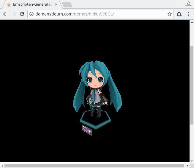
I ended up porting Mika to WebGL using SDL 1 and Emscripten.

Next I will describe what needed to be changed in the code so that the assembly in JavaScript would complete successfully.

  1. Use SDL 1 instead of SDL 2. There is currently a port of SDL 2 for emscripten, but I found it more appropriate to use the built-in emscripten SDL 1. The context is initialized not in the window, but with SDL_SetVideoMode and the SDL_OPENGL flag. The buffer is drawn with the SDL_GL_SwapBuffers() command
  2. Due to the peculiarities of execution of cycles in JavaScript – rendering is moved to a separate function and its periodic call is set using the function emscripten_set_main_loop
  3. Also, the assembly must be carried out with the key “-s FULL_ES2=1
  4. I had to abandon the assimp library, loading the model from the file system, loading the texture from the disk. All the necessary buffers were loaded onto the desktop version, and passed to the c-header file for assembly using emscripten.

Code:
https://github.com/demensdeum/OpenGLES3-Experiments/tree/master/9-sdl-gles-obj-textured-assimp-miku-webgl/mikuWebGL

Articles:
http://blog.scottlogic.com/2014/03/12/native-code-emscripten-webgl-simmer-gently.html
https://kripken.github.io/emscripten-site/docs/porting/multimedia_and_graphics/OpenGL-support.html

Model:
https://sketchfab.com/models/7310aaeb8370428e966bdcff414273e7

There is only Miku

Result of work on FSGL library with OpenGL ES and code:

Next I will describe how all this was programmed, and how various interesting problems were solved.

First we initialize the OpenGL ES context, as I wrote in the previous note. Further we will consider only rendering, a brief description of the code.

The Matrix is ​​watching you

This Miku figure in the video is made up of triangles. To draw a triangle in OpenGL, you need to specify three points with x, y, z coordinates in the 2D coordinates of the OpenGL context.
Since we need to draw a figure containing 3D coordinates, we need to use the projection matrix. We also need to rotate, zoom, or do anything with the model – for this, the model matrix is used. There is no concept of a camera in OpenGL, in fact, objects rotate around a static camera. For this, the view matrix is used.

To simplify the implementation of OpenGL ES – it does not have matrix data. You can use libraries that add missing functionality, such as GLM.

Shaders

In order to allow the developer to draw whatever and however he wants, it is necessary to implement vertex and fragment shaders in OpenGL ES. A vertex shader must receive rendering coordinates as input, perform transformations using matrices, and pass the coordinates to gl_Position. A fragment or pixel shader – already draws the color/texture, applies overlay, etc.

I wrote the shaders in GLSL. In my current implementation, the shaders are embedded directly into the main application code as C strings.

Buffers

The vertex buffer contains the coordinates of the vertices (vertices), this buffer also receives coordinates for texturing and other data necessary for shaders. After generating the vertex buffer, you need to bind a pointer to the data for the vertex shader. This is done with the glVertexAttribPointer command, where you need to specify the number of elements, a pointer to the beginning of the data and the step size that will be used to walk through the buffer. In my implementation, the binding of vertex coordinates and texture coordinates for the pixel shader is done. However, it is worth mentioning that the transfer of data (texture coordinates) to the fragment shader is carried out through the vertex shader. For this, the coordinates are declared using varying.

In order for OpenGL to know in what order to draw the points for triangles – you need an index buffer (index). The index buffer contains the number of the vertex in the array, with three such indices you get a triangle.

Textures

First, you need to load/generate a texture for OpenGL. For this, I used SDL_LoadBMP, the texture is loaded from a bmp file. However, it is worth noting that only 24-bit BMPs are suitable, and the colors in them are not stored in the usual RGB order, but in BGR. That is, after loading, you need to replace the red channel with blue.
Texture coordinates are specified in the UV format, i.e. it is necessary to transmit only two coordinates. The texture is output in the fragment shader. To do this, it is necessary to bind the texture to the fragment shader.

Nothing extra

Since, according to our instructions, OpenGL draws 3D via 2D – then to implement depth and sampling of invisible triangles – we need to use sampling (culling) and a depth buffer (Z-Buffer). In my implementation, I managed to avoid manual generation of the depth buffer using two commands glEnable(GL_DEPTH_TEST); and sampling glEnable(GL_CULL_FACE);
Also, be sure to check that the near plane for the projection matrix is ​​greater than zero, since depth checking with a zero near plane will not work.

Rendering

To fill the vertex buffer, index buffer with something conscious, for example the Miku model, you need to load this model. For this, I used the assimp library. Miku was placed in a Wavefront OBJ file, loaded using assimp, and data conversion from assimp to vertex, index buffers was implemented.

Rendering takes place in several stages:

  1. Rotate Miku using the model matrix rotation
  2. Clearing the screen and depth buffer
  3. Drawing triangles using the glDrawElements command.

The next step is to implement WebGL rendering using Emscripten.

Source code:
https://github.com/demensdeum/OpenGLES3-Experiments/tree/master/8-sdl-gles-obj-textured-assimp-miku
Model:
https://sketchfab.com/models/7310aaeb8370428e966bdcff414273e7


Project it

Having drawn a red teapot in 3D, I consider it my duty to briefly describe how it is done.

Modern OpenGL does not draw 3D, it only draws triangles, points, etc. in 2D screen coordinates.
To output anything with OpenGL, you need to provide a vertex buffer, write a vertex shader, add all the necessary matrices (projection, model, view) to the vertex shader, link all the input data to the shader, call the rendering method in OpenGL. Seems simple?


Ok, what is a vertex buffer? A list of coordinates to draw (x, y, z)
The vertex shader tells the GPU what coordinates to draw.
A pixel shader tells what to draw (color, texture, blending, etc.)
Matrices translate 3D coordinates into 2D coordinates OpenGL can render

In the following articles I will provide code examples and the result.

SDL2 – OpenGL ES

I love Panda3D game engine. But right now this engine is very hard to compile and debug on Microsoft Windows operation system. So as I said some time ago, I begin to develop my own graphics library. Right now it’s based on OpenGL ES and SDL2.
In this article I am going to tell how to initialize OpenGL ES context and how SDL2 helps in this task. We are going to show nothing.

King Nothing

First of all you need to install OpenGL ES3 – GLES 3 libraries. This operation is platform dependant, for Ubuntu Linux you can just type sudo apt-get install libgles2-mesa-dev. To work with OpenGL you need to initialize OpenGL context. There is many ways to do that, by using one of libraries – SDL2, GLFW, GLFM etc. Actually there is no one right way to initialize OpenGL context, but I chose SDL2 because it’s cross-platform solution, code will look same for Windows/*nix/HTML5/iOS/Android/etc.

To install sdl2 on Ubuntu use this command sudo apt-get install libsdl2-dev

So here is OpenGL context initialization code with SDL2:

    SDL_Window *window = SDL_CreateWindow(
            "SDL2 - OGLES",
            SDL_WINDOWPOS_UNDEFINED,
            SDL_WINDOWPOS_UNDEFINED,
            640,
            480,
            SDL_WINDOW_OPENGL
            );
	    

    SDL_GLContext glContext = SDL_GL_CreateContext(window);

After that, you can use any OpenGL calls in that context.

Here is example code for this article:
https://github.com/demensdeum/OpenGLES3-Experiments/tree/master/3sdl-gles
https://github.com/demensdeum/OpenGLES3-Experiments/blob/master/3sdl-gles/sdlgles.cpp

You can build and test it with command cmake . && make && ./SDLGles