In this note I will describe the algorithm for converting an RGB buffer to grayscale.
And this is done quite simply, each pixel of the buffer’s color channel is transformed according to a certain formula and the output is a gray image.
Average method:
red = average;
green = average;
blue = average;
Складываем 3 цветовых канала и делим на 3.


Однако существует еще один метод – метод средневзвешенный, он учитывает цветовосприятие человека:
red = luminance;
green = luminance;
blue = luminance;

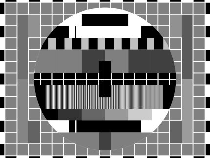
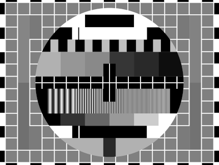
Какой метод лучше использовать? Да какой вам больше подходит для конкретной задачи. Далее сравнение методов с помощью тестовой цветовой сетки:

Пример реализации на JavaScript + HTML 5
    image,
    canvas,
    weightedAverage
) {
    const context = canvas.getContext('2d');

    const imageWeight = image.width;
    const imageHeight = image.height;

    canvas.width = imageWeight;
    canvas.height = imageHeight;

    context.drawImage(image, 0, 0);

    let pixels = context
        .getImageData(
            0,
            0,
            imageWeight,
            imageHeight
        );

    for (let y = 0; y & lt; pixels.height; y++) {
        for (let x = 0; x & lt; pixels.width; x++) {
            const i = (y * 4) * pixels.width + x * 4;

            let red = pixels.data[i];
            let green = pixels.data[i + 1];
            let blue = pixels.data[i + 2]

            const average = (red + green + blue) / 3;
            const luminance = 0.2126 * red +
                0.7152 * green +
                0.0722 * blue;

            red = weightedAverage ? luminance : average;
            green = weightedAverage ? luminance : average;
            blue = weightedAverage ? luminance : average;

            pixels.data[i] = red;
            pixels.data[i + 1] = green;
            pixels.data[i + 2] = blue;
        }
    }
    context
        .putImageData(
            pixels,
            0,
            0,
            0,
            0,
            pixels.width,
            pixels.height
        );
}
Источники
https://www.baeldung.com/cs/convert-rgb-to-grayscale
https://twitter.com/mudasobwa/status/1528046455587495940
https://rosettacode.org/wiki/Grayscale_image
Ссылки
http://papugi.demensdeum.repl.co/
Благодарности
Спасибо Aleksei Matiushkin (https://twitter.com/mudasobwa) за наводку на Rosetta Code
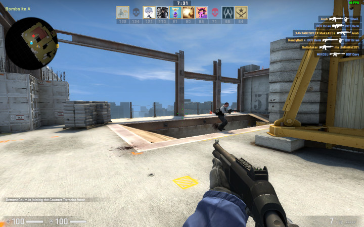
How to Run CSGO on Macbook M1
Turing Bomb
In 1936, scientist Alan Turing in his publication “On Computable Numbers, With An Application to Entscheidungsproblem” describes the use of a universal computing machine that could put an end to the question of the solvability problem in mathematics. As a result, he comes to the conclusion that such a machine would not be able to solve anything correctly if the result of its work was inverted and looped back to itself. It turns out that it is impossible to create an *ideal* antivirus, an *ideal* tile layer, a program that suggests ideal phrases for your crash, etc. Paradox!
However, this universal computing machine can be used to implement any algorithm, which is what British intelligence took advantage of by hiring Turing and allowing him to create the “Bombe” machine to decipher German messages during World War II.
The following is an OOP simulation of a single-tape computer in Dart, based on the original document.
A Turing machine consists of a film divided into sections, each section contains a symbol, the symbols can be read or written. An example of a film class:
final _map = Map<int, String>();

  String read({required int at}) {
    return _map[at] ?? "";
  }

  void write({required String symbol, required int at}) {
    _map[at] = symbol;
  }
}
There is also a “scanning square”, it can move along the film, read or write information, in modern language – a magnetic head. An example of a magnetic head class:
  int _index = 0;
  InfiniteTape _infiniteTape;
  TapeHead(this._infiniteTape) {}

  String next() {
    _index += 1;
    move(to: _index);
    final output = read();
    return output;
  }

  String previous() {
    _index -= 1;
    move(to: _index);
    final output = read();
    return output;
  }

  void move({required int to}) {
    this._index = to;
  }

  String read() {
    return _infiniteTape.read(at: this._index);
  }

  void write(String symbol) {
    _infiniteTape.write(symbol: symbol, at: this._index);
  }

  int index() {
    return _index;
  }
}
The machine contains “m-configurations” by which it can decide what to do next. In modern language, these are states and state handlers. An example of a state handler:
  FiniteStateControlDelegate? delegate = null;

  void handle({required String symbol}) {
    if (symbol == OPCODE_PRINT) {
      final argument = delegate?.nextSymbol();
      print(argument);
    }
    else if (symbol == OPCODE_GENERATE_RANDOM_NUMBER_FROM_ZERO_TO_AND_WRITE_AFTER) {
      final to = int.tryParse(delegate!.nextSymbol())!;
      final value = new Random().nextInt(to);
      delegate!.nextSymbol();
      delegate!.write(value.toString());
    }
    else if (symbol == OPCODE_INPUT_TO_NEXT) {
      final input = stdin.readLineSync()!;
      delegate?.nextSymbol();
      delegate?.write(input);
    }
    else if (symbol == OPCODE_COPY_FROM_TO) {
      final currentIndex = delegate!.index();

и т.д.
After this, you need to create “configurations”, in modern language these are operation codes (opcodes), their handlers. An example of opcodes:
const OPCODE_PRINT = "print";
const OPCODE_INCREMENT_NEXT = "increment next";
const OPCODE_DECREMENT_NEXT = "decrement next";
const OPCODE_IF_PREVIOUS_NOT_EQUAL = "if previous not equal";
const OPCODE_MOVE_TO_INDEX = "move to index";
const OPCODE_COPY_FROM_TO = "copy from index to index";
const OPCODE_INPUT_TO_NEXT = "input to next";
const OPCODE_GENERATE_RANDOM_NUMBER_FROM_ZERO_TO_AND_WRITE_AFTER = "generate random number from zero to next and write after";
Don’t forget to create an opcode and a stop handler, otherwise you won’t be able to prove or not prove (sic!) the resolution problem.
Now, using the “mediator” pattern, we connect all the classes in the Turing Machine class, create an instance of the class, record the programs on tape using a tape recorder, load the tape and you can use it!
For me personally, the question of what came first remains interesting: the creation of a universal computer or the proof of the “Entscheidungsproblem”, which resulted in the computer appearing as a by-product.
Cassettes
For fun, I recorded several cassette programs for my version of the machine.
Hello World
hello world
stop
Считаем до 16-ти
0
if previous not equal
16
copy from index to index
1
8
print
?
move to index
0
else
copy from index to index
1
16
print
?
print
Finished!
stop
Самой интересной задачей было написание Quine программы, которая печатает свой исходный код, для одноленточной машины. Первые 8 часов мне казалось что эта задача не решаема с таким малым количеством опкодов, однако всего через 16 часов оказалось что я был не прав.
Реализация и примеры кассет, источники ниже.
Ссылки
https://gitlab.com/demensdeum/turing-machine
Источники
https://www.astro.puc.cl/~rparra/tools/PAPERS/turing_1936.pdf
https://kpolyakov.spb.ru/prog/turing.htm
https://www.youtube.com/watch?v=dNRDvLACg5Q
https://www.youtube.com/watch?v=jP3ceURvIYc
https://www.youtube.com/watch?v=9QCJj5QzETI
https://www.youtube.com/watch?v=HeQX2HjkcNo&t=0s
Writing Assembler for Sega Genesis #5
In this post I will describe the process of reading the joystick, changing the sprite position, horizontal flip, Sega Genesis emulator and potentially the console itself.
Reading of presses, processing of “events” of the Sega joystick occurs according to the following scheme:
- Request for combination of bits of pressed buttons
- Reading bits of pressed buttons
- Processing at the game logic level
To move the skeleton sprite we need to store the current position variables.
RAM
Game logic variables are stored in RAM, people haven’t come up with anything better yet. Let’s declare variable addresses, change the rendering code:
skeletonYpos = $FF0002
frameCounter = $FF0004
skeletonHorizontalFlip = $FF0006

    move.w #$0100,skeletonXpos
    move.w #$0100,skeletonYpos
    move.w #$0001,skeletonHorizontalFlip

FillSpriteTable:
    move.l #$70000003,vdp_control_port
    move.w skeletonYpos,vdp_data_port
    move.w #$0F00,vdp_data_port
    move.w skeletonHorizontalFlip,vdp_data_port
    move.w skeletonXpos,vdp_data_port
As you can see, the address available for work starts at 0xFF0000 and ends at 0xFFFFFF, so we have 64 KB of memory available. Skeleton positions are declared at skeletonXpos, skeletonYpos, horizontal flip at skeletonHorizontalFlip.
Joypad
Similar to VDP, joypads are handled via two separate ports – the control port and the data port, for the first one it’s 0xA10009 and 0xA10003 respectively. When working with a joypad, there’s one interesting feature – first you need to request a combination of buttons for polling, and then, after waiting for the bus update, read the required presses. For the C/B buttons and the cross, it’s 0x40, an example below:
  move.b #$40,joypad_one_control_port; C/B/Dpad
  nop ; bus sync
  nop ; bus sync
  move.b joypad_one_data_port,d2
  rts
The state of the buttons pressed or not pressed will remain in the d2 register, in general, what was requested via the data port will remain. After that, go to the Motorola 68000 register viewer of your favorite emulator, see what the d2 register is equal to depending on the presses. You can find this out in the manual in a smart way, but we don’t take your word for it. Next, processing the pressed buttons in the d2 register
    cmp #$FFFFFF7B,d2; handle left
    beq MoveLeft
    cmp #$FFFFFF77,d2; handle right
    beq MoveRight
    cmp #$FFFFFF7E,d2; handle up
    beq MoveUp
    cmp #$FFFFFF7D,d2; handle down
    beq MoveDown
    rts
Проверять нужно конечно отдельные биты, а не целыми словами, но пока и так сойдет. Теперь осталось самое простое – написать обработчики всех событий перемещения по 4-м направлениям. Для этого меняем переменные в RAM, и запускаем процедуру перерисовки.
Пример для перемещения влево + изменение горизонтального флипа:
    move.w skeletonXpos,d0
    sub.w #1,d0
    move.w d0,skeletonXpos
    move.w #$0801,skeletonHorizontalFlip
    jmp FillSpriteTable
После добавления всех обработчиков и сборки, вы увидите как скелет перемещается и поворачивается по экрану, но слишком быстро, быстрее самого ежа Соника.
Не так быстро!
Чтобы замедлить скорость игрового цикла, существуют несколько техник, я выбрал самую простую и не затрагивающую работу с внешними портами – подсчет цифры через регистр пока она не станет равна нулю.
Пример замедляющего цикла и игрового цикла:
  move.w #512,frameCounter
WaitFrame:
  move.w frameCounter,d0
  sub.w #1,d0
  move.w d0,frameCounter
  dbra d0,WaitFrame
GameLoop:
  jsr ReadJoypad
  jsr HandleJoypad
  jmp GameLoop
After that, the skeleton runs slower, which is what was required. As far as I know, the most common option for “slowing down” is counting the vertical sync flag, you can count how many times the screen was drawn, thus tying it to a specific fps.
Links
https://gitlab .com/demensdeum/segagenesisamples/-/blob/main/8Joypad/vasm/main.asm
Sources
https://www.chibiakumas.com/68000/platform2.php
https://huguesjohnson.com/programming/genesis/tiles-sprites/
Writing Assembler for Sega Genesis #4
In this note I will describe how to draw sprites using the VDP emulator of the Sega Genesis console.
The process of rendering sprites is very similar to rendering tiles:
- Loading colors into CRAM
- Unloading 8×8 sprite parts into VRAM
- Filling Sprite Table in VRAM
For example, let’s take a sprite of a skeleton with a sword 32×32 pixels![]()
Skeleton Guy [Animated] by Disthorn
CRAM
Using ImaGenesis we will convert it into CRAM colors and VRAM patterns for assembler. After that we will get two files in asm format, then we will rewrite the colors to word size, and the tiles should be put in the correct order for drawing.
Interesting information: you can switch the VDP autoincrement via register 0xF to the word size, this will allow you to remove the address increment from the CRAM color fill code.
VRAM
The Sega manual has the correct tile order for large sprites, but we’re smarter, so we’ll take the indexes from the ChibiAkumas blog, starting the count from index 0:
0 4 8 12
1 5 9 13
2 6 10 14
3 7 11 15
Why is everything upside down? What do you expect, the prefix is Japanese! It could have been from right to left!
Let’s change the order manually in the sprite asm file:
	dc.l	$11111111	; Tile #0
	dc.l	$11111111
	dc.l	$11111111
	dc.l	$11111111
	dc.l	$11111111
	dc.l	$11111111
	dc.l	$11111111
	dc.l	$11111111
	dc.l	$11111111	; Tile #4
	dc.l	$11111111
	dc.l	$11111111
	dc.l	$11111111
	dc.l	$11111111
	dc.l	$11111111
	dc.l	$11111111
	dc.l	$11111111
	dc.l	$11111111	; Tile #8
	dc.l	$11111111
	dc.l	$11111111
	dc.l	$11111111
	dc.l	$11111111
	dc.l	$11111122
	dc.l	$11111122
	dc.l	$11111166
	dc.l	$11111166	; Tile #12
	dc.l	$11111166
	dc.l	$11111166
	и т.д.
Load the sprite like regular tiles/patterns:
  lea Sprite,a0
  move.l #$40200000,vdp_control_port; write to VRAM command
  move.w #128,d0 ; (16*8 rows of sprite) counter
SpriteVRAMLoop:
  move.l (a0)+,vdp_data_port;
  dbra d0,SpriteVRAMLoop
To draw the sprite, it remains to fill the sprite table (Sprite Table)
Sprite Table
The sprite table is filled in VRAM, its location address is set in VDP register 0x05, the address is again tricky, you can look it up in the manual, an example for address F000:
Ок, теперь запишем наш спрайт в таблицу. Для этого нужно заполнить “структуру” данных состоящую из четырех word. Бинарное описание структуры вы можете найти в мануале. Лично я сделал проще, таблицу спрайтов можно редактировать вручную в эмуляторе Exodus.![]()
The parameters of the structure are obvious from the name, for example XPos, YPos – coordinates, Tiles – the number of the starting tile for drawing, HSize, VSize – the size of the sprite by adding parts 8×8, HFlip, VFlip – hardware rotations of the sprite horizontally and vertically.![]()
It is very important to remember that sprites can be off-screen, this is correct behavior, since unloading off-screen sprites from memory is quite a resource-intensive task.
After filling the data in the emulator, it needs to be copied from VRAM to address 0xF000, Exodus also supports this feature.
By analogy with drawing tiles, first we access the VDP control port to start writing at address 0xF000, then we write the structure to the data port.
Let me remind you that the description of VRAM addressing can be read in the manual or in the blog Nameless Algorithm.
In short, VDP addressing works like this:
[..DC BA98 7654 3210 …. …. …. ..FE]
Where hex is the bit position in the desired address. The first two bits are the type of command requested, for example 01 – write to VRAM. Then for address 0XF000 you get:
0111 0000 0000 0000 0000 0000 0000 0011 (70000003)
As a result we get the code:
  move.l #$70000003,vdp_control_port
  move.w #$0100,vdp_data_port
  move.w #$0F00,vdp_data_port
  move.w #$0001,vdp_data_port
  move.w #$0100,vdp_data_port
After this, the skeleton sprite will be displayed at coordinates 256, 256. Cool, huh?
Links
https://gitlab.com/demensdeum /segagenesissamples/-/tree/main/7Sprite/vasm
https://opengameart.org/content/skeleton-guy-animated
Sources
https://namelessalgorithm.com/genesis/blog/vdp/
https://www.chibiakumas.com/68000/platform3.php#LessonP27
https://plutiedev.com/sprites
Writing Assembler for Sega Genesis #3
In this note I will describe how to display an image from tiles on the Sega Genesis emulator using assembler.
The splash image Demens Deum in the Exodus emulator will look like this:
![]()
The process of outputting a PNG image using tiles is done step by step:
- Reduce image to fit Sega screen
- Convert PNG to assembly data code, with separation into colors and tiles
- Loading color palette into CRAM
- Loading tiles/patterns into VRAM
- Loading tile indices to Plane A/B addresses into VRAM
- You can reduce the image to the size of the Sega screen using your favorite graphics editor, such as Blender.
PNG conversion
To convert images, you can use the ImaGenesis tool, to work under wine, you need Visual Basic 6 libraries, they can be installed using winetricks (winetricks vb6run), or RICHTX32.OCX can be downloaded from the Internet and placed in the application folder for correct operation.
In ImaGenesis, you need to select 4-bit color, export colors and tiles to two assembler files. Then, in the file with colors, you need to put each color into a word (2 bytes), for this, the opcode dc.w is used.
For example CRAM splash screen:
  dc.w $0000
  dc.w $0000
  dc.w $0222
  dc.w $000A
  dc.w $0226
  dc.w $000C
  dc.w $0220
  dc.w $08AA
  dc.w $0446
  dc.w $0EEE
  dc.w $0244
  dc.w $0668
  dc.w $0688
  dc.w $08AC
  dc.w $0200
  dc.w $0000
Leave the tile file as is, it already contains the correct format for loading. Example of part of the tile file:
	dc.l	$11111111	; Tile #0
	dc.l	$11111111
	dc.l	$11111111
	dc.l	$11111111
	dc.l	$11111111
	dc.l	$11111111
	dc.l	$11111111
	dc.l	$11111111
	dc.l	$11111111	; Tile #1
	dc.l	$11111111
	dc.l	$11111111
	dc.l	$11111111
	dc.l	$11111111
	dc.l	$11111111
	dc.l	$11111111
	dc.l	$11111111
As you can see from the example above, the tiles are an 8×8 grid of CRAM color palette indices.
Colors in CRAM
Loading into CRAM is done by setting the color load command at a specific CRAM address in the control port (vdp control). The command format is described in the Sega Genesis Software Manual (1989), I will only add that it is enough to add 0x20000 to the address to move to the next color.
Next, you need to load the color into the data port (vdp data); The easiest way to understand the loading is with the example below:
    lea Colors,a0 ; pointer to Colors label
    move.l #15,d7; colors counter
VDPCRAMFillLoopStep:
    move.l  d0,vdp_control_port ;
    move.w  (a0)+,d1;
    move.w  d1,(vdp_data_port);
    add.l #$20000,d0 ; increment CRAM address
    dbra d7,VDPCRAMFillLoopStep
Tiles in VRAM
Next comes loading of tiles/patterns into the VRAM video memory. To do this, select an address in VRAM, for example 0x00000000. By analogy with CRAM, we address the VDP control port with a command to write to VRAM and the starting address.
After that, you can upload longwords to VRAM, compared to CRAM, you do not need to specify the address for each longword, since there is a VRAM autoincrement mode. You can enable it using the VDP register flag 0x0F (dc.b $02)
  lea Tiles,a0
  move.l #$40200000,vdp_control_port; write to VRAM command
  move.w #6136,d0 ; (767 tiles * 8 rows) counter
TilesVRAMLoop:
  move.l (a0)+,vdp_data_port;
  dbra d0,TilesVRAMLoop
Tile indexes in Plane A/B
Now we need to fill the screen with tiles by their index. To do this, fill the VRAM at the address Plane A/B, which is set in the VDP registers (0x02, 0x04). More details about the tricky addressing are in the Sega manual, in my example the VRAM address is 0xC000, we will unload the indices there.
Your image will fill the off-screen VRAM space anyway, so after drawing the screen space, your renderer should stop drawing and continue again when the cursor moves to a new line. There are many options for how to implement this, I used the simplest option of counting on two registers of the image width counter, the cursor position counter.
Code example:
  move.w #0,d0     ; column index
  move.w #1,d1     ; tile index
  move.l #$40000003,(vdp_control_port) ; initial drawing location
  move.l #2500,d7     ; how many tiles to draw (entire screen ~2500)

imageWidth = 31
screenWidth = 64

FillBackgroundStep:
  cmp.w	#imageWidth,d0
  ble.w	FillBackgroundStepFill
FillBackgroundStep2:
  cmp.w	#imageWidth,d0
  bgt.w	FillBackgroundStepSkip
FillBackgroundStep3:
  add #1,d0
  cmp.w	#screenWidth,d0
  bge.w	FillBackgroundStepNewRow
FillBackgroundStep4:
  dbra d7,FillBackgroundStep    ; loop to next tile

Stuck:
  nop
  jmp Stuck

FillBackgroundStepNewRow:
  move.w #0,d0
  jmp FillBackgroundStep4
FillBackgroundStepFill:
  move.w d1,(vdp_data_port)    ; copy the pattern to VPD
  add #1,d1
  jmp FillBackgroundStep2
FillBackgroundStepSkip:
  move.w #0,(vdp_data_port)    ; copy the pattern to VPD
  jmp FillBackgroundStep3
After that, all that remains is to compile the ROM using vasm, run the simulator, and see the picture.
Debugging
Not everything will work out right away, so I want to recommend the following Exodus emulator tools:
- m68k processor debugger
- Changing the number of m68k processor cycles (for slow-mo mode in the debugger)
- Viewers CRAM, VRAM, Plane A/B
- Carefully read the documentation for m68k, the opcodes used (not everything is as obvious as it seems at first glance)
- View code/disassembly examples of games on github
- Implement subroutines of processor exceptions, handle them
Pointers to subroutines of processor exceptions are placed in the ROM header, also on GitHub there is a project with an interactive runtime debugger for Sega, called genesis-debugger.
Use all the tools available, have fun old school coding and may Blast Processing be with you!
Links
https://gitlab.com/demensdeum /segagenesisamples/-/tree/main/6Image/vasm
http://devster.monkeeh.com/sega/imagenesis/
https://github.com/flamewing/genesis-debugger
Sources
https://www.chibiakumas.com/68000/helloworld .php#LessonH5
https://huguesjohnson.com/programming/genesis/tiles-sprites/
Writing Assembler for Sega Genesis #2
In this note I will describe how to load colors into the Sega palette in assembler.
The final result in the Exodus emulator will look like this: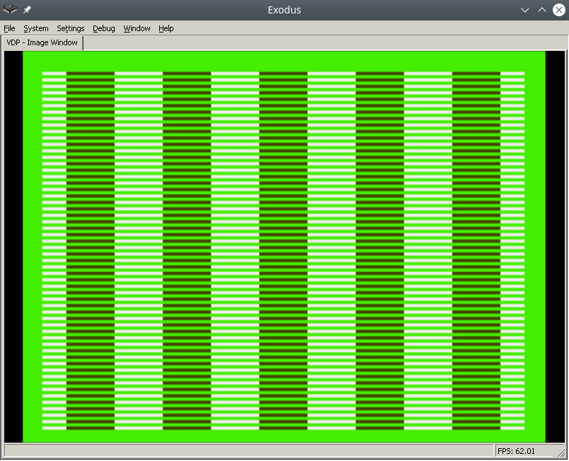
To make the process easier, find a pdf online called Genesis Software Manual (1989), it describes the whole process in great detail, in fact, this note is a commentary on the original manual.
In order to write colors to the VDP chip of the Sega emulator, you need to do the following:
- Disable TMSS protection system
- Write the correct parameters to the VDP registers
- Write the desired colors to CRAM
For assembly we will use vasmm68k_mot and a favorite text editor, for example echo. Assembly is carried out by the command:
Порты VDP
VDP чип общается с M68K через два порта в оперативной памяти – порт контроля и порт данных.
По сути:
- Через порт контроля можно выставлять значения регистрам VDP.
- Также порт контроля является указателем на ту часть VDP (VRAM, CRAM, VSRAM etc.) через которую передаются данные через порт данных
Интересная информация: Сега сохранила совместимость с играми Master System, на что указывает MODE 4 из мануала разработчика, в нем VDP переключается в режим Master System.
Объявим порты контроля и данных:
vdp_data_port = $C00000
Отключить систему защиты TMSS
Защита от нелицензионных игр TMSS имеет несколько вариантов разблокировки, например требуется чтобы до обращения к VDP в адресном регистре A1 лежала строка “SEGA”.
MOVE.B A1,D0; Получаем версию хардвары цифрой из A1 в регистр D0
ANDI.B 0x0F,D0; По маске берем последние биты, чтобы ничего не сломать
BEQ.B SkipTmss; Если версия равна 0, скорее всего это японка или эмулятор без включенного TMSS, тогда идем в сабрутину SkipTmss
MOVE.L "SEGA",A1; Или записываем строку SEGA в A1
Write the correct parameters to the VDP registers
Why set the correct parameters in the VDP registers at all? The idea is that the VDP can do a lot, so before drawing you need to initialize it with the necessary features, otherwise it simply won't understand what you want from it.
Each register is responsible for a specific setting/operating mode. The Sega manual specifies all the bits/flags for each of the 24 registers, and a description of the registers themselves.
Let's take ready-made parameters with comments from the bigevilcorporation blog:
VDPReg0: dc.b $14 ; 0: H interrupt on, palettes on
VDPReg1: dc.b $74 ; 1: V interrupt on, display on, DMA on, Genesis mode on
VDPReg2: dc.b $30 ; 2: Pattern table for Scroll Plane A at VRAM $C000
; (bits 3-5 = bits 13-15)
VDPReg3: dc.b $00 ; 3: Pattern table for Window Plane at VRAM $0000
; (disabled) (bits 1-5 = bits 11-15)
VDPReg4: dc.b $07 ; 4: Pattern table for Scroll Plane B at VRAM $E000
; (bits 0-2 = bits 11-15)
VDPReg5: dc.b $78 ; 5: Sprite table at VRAM $F000 (bits 0-6 = bits 9-15)
VDPReg6: dc.b $00 ; 6: Unused
VDPReg7: dc.b $00 ; 7: Background colour - bits 0-3 = colour,
; bits 4-5 = palette
VDPReg8: dc.b $00 ; 8: Unused
VDPReg9: dc.b $00 ; 9: Unused
VDPRegA: dc.b $FF ; 10: Frequency of Horiz. interrupt in Rasters
; (number of lines travelled by the beam)
VDPRegB: dc.b $00 ; 11: External interrupts off, V scroll fullscreen,
; H scroll fullscreen
VDPRegC: dc.b $81 ; 12: Shadows and highlights off, interlace off,
; H40 mode (320 x 224 screen res)
VDPRegD: dc.b $3F ; 13: Horiz. scroll table at VRAM $FC00 (bits 0-5)
VDPRegE: dc.b $00 ; 14: Unused
VDPRegF: dc.b $02 ; 15: Autoincrement 2 bytes
VDPReg10: dc.b $01 ; 16: Vert. scroll 32, Horiz. scroll 64
VDPReg11: dc.b $00 ; 17: Window Plane X pos 0 left
; (pos in bits 0-4, left/right in bit 7)
VDPReg12: dc.b $00 ; 18: Window Plane Y pos 0 up
; (pos in bits 0-4, up/down in bit 7)
VDPReg13: dc.b $FF ; 19: DMA length lo byte
VDPReg14: dc.b $FF ; 20: DMA length hi byte
VDPReg15: dc.b $00 ; 21: DMA source address lo byte
VDPReg16: dc.b $00 ; 22: DMA source address mid byte
VDPReg17: dc.b $80 ; 23: DMA source address hi byte,
; memory-to-VRAM mode (bits 6-7)
Okay, now let's go to the control port and write all the flags to the VDP registers:
move.l #VDPRegisters,a0 ; Пишем адрес таблицы параметров в A1
move.l #$18,d0 ; Счетчик цикла - 24 = 18 (HEX) в D0
move.l #$00008000,d1 ; Готовим команду на запись в регистр VDP по индексу 0, по мануалу - 1000 0000 0000 0000 (BIN) = 8000 (HEX)
FillInitialStateForVDPRegistersLoop:
move.b (a0)+,d1 ; Записываем в D1 итоговое значение регистра VDP из таблицы параметров, на отправку в порт контроля VDP
move.w d1,vdp_control_port ; Отправляем итоговую команду + значение из D1 в порт контроля VDP
add.w #$0100,d1 ; Поднимаем индекс регистра VDP на 1 (бинарное сложение +1 к индексу по мануалу Сеги)
dbra d0,FillInitialStateForVDPRegistersLoop ; Уменьшаем счетчик регистров, продолжаем цикл если необходимо
Самое сложное это прочитать мануал и понять в каком формате подаются данные на порт контроля, опытные разработчики разберутся сразу, а вот неопытные… Немного подумают и поймут, что синтаксис для записи регистров такой:
0B100(5 бит – индекс регистра)(8 бит/байт – значение)
0B1000001001000101 – записать в регистр VDP 2 (00010), значение флажков 01000101.
Записать нужные цвета в CRAM
Далее идем писать два цвета в память цветов CRAM (Color RAM). Для этого пишем в порт контроля команду на доступ к цвету по индексу 0 в CRAM и отправляем по дата порту цвет. Все!
Пример:
move.l #$C0000000,vdp_control_port ; Доступ к цвету по индексу 0 в CRAM через порт контроля
move.w #228,d0; Цвет в D0
move.w d0,vdp_data_port; Отправляем цвет в порт данных
After building and running in the emulator in Exodus, you should have a screen filled with color 228.
Let's fill it with a second color, at the last byte 127.
move.l #$C07f0000,vdp_control_port ; Доступ к цвету по байту 127 в CRAM через порт контроля
move.w #69,d0; Цвет в D0
move.w d0,vdp_data_port; Отправляем цвет в порт данных
Links
https://gitlab.com/demensdeum/segagenesissamples
https://www.exodusemulator.com/
http://sun.hasenbraten.de/vasm/
https://tomeko.net/online_tools/bin_to_32bit_hex.php?lang=en
Sources
https://namelessalgorithm.com/genesis/blog/genesis/
https://plutiedev.com/vdp-commands
https://huguesjohnson.com/programming/genesis/palettes/
https://www.chibiakumas.com/68000/helloworld.php#LessonH5
https://blog.bigevilcorporation.co.uk/2012/03/09/sega-megadrive-3-awaking-the-beast/
Writing Assembler for Sega Genesis #1
The first article dedicated to writing games for the classic Sega Genesis console in Motorola 68000 Assembler.
Let’s write the simplest infinite loop for Sega. For this we will need: assembler, emulator with disassembler, favorite text editor, basic understanding of Sega ROM structure.
For development, I use my own assembler/Dizassembler GEN68KRYBABY:
https://gitlab.com/demensdeum/gen68krybaby/
The tool is developed in Python 3, for assembly a file with the extension .asm or .gen68KryBabyDisasm is fed to the input, the output is a file with the extension .gen68KryBabyAsm.bin, which can be run in an emulator or on a real console (be careful, move away, the console may explode!)
ROM disassembly is also supported, for this you need to supply a ROM file to the input, without the .asm or .gen68KryBabyDisasm extensions. Opcode support will increase or decrease depending on my interest in the topic, the participation of contributors.
Structure
The Sega ROM header takes up the first 512 bytes. It contains information about the game, the title, supported peripherals, checksum, and other system flags. I assume that without the header, the console won’t even look at the ROM, thinking that it’s invalid, like “what are you giving me here?”
After the header comes the Reset subroutine/subprogram, with it the m68K processor starts working. Okay, now it’s a small matter – find the opcodes (operation codes), namely, doing nothing(!) and jumping to the subroutine at the address in memory. Googling, you can find the NOP opcode, which does nothing, and the JSR opcode, which performs an unconditional jump to the argument address, that is, it simply moves the carriage where we ask it to, without any whims.
Putting it all together
The title donor for the ROM was one of the games in the Beta version, currently written as hex data.
00 ff 2b 52 00 00 02 00 00 00 49 90 00 00 49 90 00 00 49 90 00...и т.д.
Код программы со-но представляет из себя объявление сабрутины Reset/EntryPoint в 512 (0x200) байте, NOP, возврат каретки к 0x00000200, таким образом мы получим бесконечный цикл.
Ассемблерный код сабрутины Reset/EntryPoint:
NOP
NOP
NOP
NOP
NOP
JSR 0x00000200
Full example with rom title:
https://gitlab.com /demensdeum/segagenesisamples/-/blob/main/1InfiniteLoop/1infiniteloop.asm
Next we collect:
Запускаем ром 1infiniteloop.asm.gen68KryBabyAsm.bin в режиме дебаггера эмулятора Exodus/Gens, смотрим что m68K корректно считывает NOP, и бесконечно прыгает к EntryPoint в 0x200 на JSR
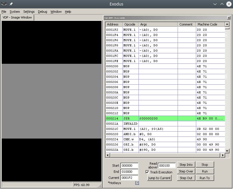
Здесь должен быть Соник показывающий V, но он уехал на Вакен.
Ссылки
https://gitlab.com/demensdeum/gen68krybaby/
https://gitlab.com/demensdeum/segagenesissamples
https://www.exodusemulator.com/downloads/release-archive
Источники
ROM Hacking Demo – Genesis and SNES games in 480i
https://www.chibiakumas.com/68000/genesis.php
https://plutiedev.com/rom-header
https://blog.bigevilcorporation.co.uk/2012/02/28/sega-megadrive-1-getting-started/
https://opensource.apple.com/source/cctools/cctools-836/as/m68k-opcode.h.auto.html